

UPDATE 20/9/2020 This item is FOR SALE on Ebay UK Item Number : 254724509989
Here is a short video from Toaday Sunday 20th September with the radio tuned to Shanwick Oceanic Volmet Weather on 5.505 USB.
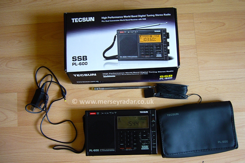
The Tecsun PL-600 is a great HF radio for the price, some time ago I gave a thumbs up for it on my local aviation forum.
A really good beginner HF radio, it has all you need without much in the way of financial outlay.
The PL-600 Comes with all the bits you need to get going including 4 AA ni-cad batteries, long wire antenna and a neat little case.
There is a healthy second hand market for Tecsun PL-6xx and PL-8xx radios so, after a while, if you decide you like what you are hearing & want to upgrade to a bigger yaseu,kenwood or icom later on, you can flip the Tecsun on ebay for close to what you paid for it .
After a few months of happy of ownership I decided to complete a modification to the AM audio circuit to improve ssb reception as sometimes, especially with strong stations, the PL-600 can get overloaded with the intended signal and poor quality audio from the speaker is the result.
Its almost as if the gain is cranked up far too much.
There are some write ups on the internet for the mod “Insert 1k resistor into audio IC at pin 18 and ground”.
Thats about it.. and a few youtube videos on the resulting audio but, Not much at all in the way of a guide as to how to take the radio apart or complete the job… Very vague indeed.
There was much talk on internet boards & forums regarding this mod, but just that.. talk .
Lets not talk…Lets do !
Oh well, nothing ventured, nothing gained..so here goes..
Lets get in there and see what we are dealing with.
Put the radio face down on a jiffy padded bag or similar to protect the front from any scratches.
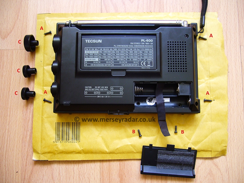
Open the radio by removing the 4 pointed screws marked A , next the 2 blunt screws from inside the battery chamber marked B. Finally pull off the 3 knobs at the side marked C.
The front bezel of the radio will come free along with the lanyard carrying string but some manipulation notes first.

The speaker is attached to the front on a very short pair of wires so you have to manipulate the front cover to get it out of the way without pulling the speaker wires out of the pcb. The front removed and speaker out of the way, you can see partly through to the main PLL/logic board. The keypad pcb is attached piggy back style to the PLL board. (More on that later).

Now remove both circuit board assemblies as one unit by levering up on one corner and gradually coax the whole lot up and out of the casing sideways. “Jockey” it slightly as you lift the whole assembly up and out of the casing. Pay particular attention to the 3 knob controls at the side, work on this side first and free the 2 boards as one unit from the rear casing.
Take care with the headphone jack, antenna jack etc, Just keep working away gradually freeing out a little at a time.

Next , the audio IC sits inside the main PLL/Logic pcb. This is joined piggy back onto the keypad pcb.
And Now you have 2 choices..
Choice 1: Get at the audio IC on component side/non solder side by removing the keypad/LCD pcb and soldering a resisitor on the audio chip itself from the front of the logic/pll board .
(I spotted a post in Russian of an owner and seasoned radio amateur who did this, it is not easy as the ground point he used was a metal shield, through the meduim of google translate, I noted he had extreme difficulty getting the keypad pcb back to its home location without damaging the new resistor junction he had just made).
I removed the entire keypad/lcd pcb, had a little look in there and immediately felt his pain. The access seems fine when the 2 boards are apart but only a wafer thin gap exists when they are put back together.
I made some notes and shut up shop again….
Choice 2 : Do the joint on the solder side of the main logic/pcb… My choice.
No contest (I thought) , option 2 it is !
Flip over the board to the solder side, the item we need is the audio IC . It is a 24 pin package. When i took a peep inside the 2 boards earlier, I noted the orientation of the IC (where pin 1 is located) I marked it with a sharpie on the solder side for reference.
The chip is a Toshiba TA2057N.
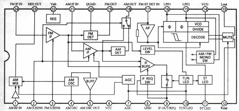
Pin 18 is the AM out ..and handy enough pin 8 on the opposite side is ground.
Solder a 1k resistor between these 2 pins on the solder side. This area is what I would call very small for hand held old school manual solder work, take your time here with a low wattage iron and liberal amounts of flux paste. The next photo shows the size of the area of the PLL board being worked on.

At this point I should say.. It is easy to trash the radio completing this stage..That factory solder is horrible, there are some SMD devices in very close proximity to “the job” so go easy on the heat.
A word on the solder used at the factory, it seems to be eco friendly rubbish or poor solder with low lead content used throughout the radio. It is Very Difficult to work with and not very forgiving.
You will note my 10x LED illuminated loupe in use and photo bombing the write up.
The joints are very small and I used the loupe to inspect for dry/bad joints and find my way around the board.
Checking the value of the resistor in situ when you are done . Use small croc clips for this job, too small an area for meter probes. I marked pin 1 from when I took a quick look at the other side earlier on. Here is a macro shot of the work area.

My fantastically reliable Chauvin Arnoux Metrix MX-26 multimeter is right on the money,it should be, so expensive when I bought it ! Calibrated annually.

Meter says good 0.996 k ohms, so thats close enough to 1k for me !
Cover adjacent board pins with tape then carefully bend the resistor down flat on top of the PVC tape cushion making sure that the junction does not come apart.

Check with a magnifier loupe and miniature podger (dressmakers needle) to make sure all is well with the joints and they are not loose or dry.

While you are here, replace the 2 speaker wires (these are poor quality) with decent thicker copper ones.
This will also improve the audio from the loudspeaker.
Solder locations are marked on the board ,SP1 and SP2.

You are limited in wire choices here by the hole size in the pcb but , with patience, you can get 3 times thicker wires in there than the originals. Keep the length the same even though this is a real pain.
The last thing you need is a pair of wires showing in the clear LCD display window when you are all boxed up !
While you are in the area, Swap out the FM antenna wire link with a thicker, longer one too.
Next put everything back first coaxing in your pcb assembly back in to the rear casing frame, antenna socket/power input side first, Make sure the pull out wire stand & reset switch sub pcb are correctly positioned at the bottom.
Lever up the corner of the PLL pcb frame about 1mm or so with a flat screwdriver & hook in the lanyard into its fixing guide. Insert a small driver in the hole to line up the casing holes/lanyard rope loop. Dont forget this bit, the rope loop goes in now or never.

Now press the PCB frame corner back down again.
Next, clean up the clear LCD window inside surface,

and also clean the the LCD glass on the display panel itself.

Ensure the display foam edge is put back right .
Clip the front bezel back on.

Check everything is in place at both sides of the radio,the switches, and knobs line up correctly and the pull out wire stand extends and retracts before replacing all the screws.

Remember to check the jacks at the side and they line up right, and reset switch at the bottom lines up with its hole in case.
Now,replace those screws, remember the “bluetac hack” it makes life a lot easier if you dont drop screws into the bech/floor/ abyss. A tiny blob on the end of your screwdriver will save you a lot of hassle.
A little bluetac goes a long way.

Replace batteries and test.

I never used the tecsun batteries supplied although they may be okay, I trust Sanyo Eneloops when plugging stuff in to charge, they are super reliable.
I Tuned on Shanwick Radio on 5.649 usb, lets link up a long wire…

I have sound.. she made it through the surgery !
The ssb received audio quality has improved significantly from stock factory reception.
A very solid 3 screwdriver job in the “Haynes manual of radio servicing”… if there was one. Quite challenging due to the poor quality factory solder used and limited space soldering and working around that 24 pin IC with those SMDs in the way.
Make no mistake, this is no Realistic Pro-2006, smd transistors, capacitors and cost cutting is evident throughout right down to the “tin can solder”.
Have fun !
Hope you enjoyed the trip in to the PL-600 and I hope someone finds this useful.
Update: Tecsun PL-600 Revisited.
Having fitted the modification I wasnt happy with mounting the resistor at the back of that main PLL PCB.
It may have stayed there for life but there was a little gremlin whispering doubt in my ear every time I used the radio, “What if you knock the radio and one of those ever so tiny tracks around the audio IC breaks clean off” ?..”What are you going to do if that happens smart ass” ?
Thinking about it, I should have perhaps applied 3m adhesive single sided foam instead of electrical tape to protect the resistor against a knock or drop of the radio.
In the end , The prospect of mounting the additional component on the reverse (non solder) side seemed increasingly more attractive. I mentioned earlier that a Tecsun owner from Russia had done his this way using just the wire tails of the resistor itself but he had extreme difficulty with space constraints when re assembling the radio. He was a seasoned hobby technician,radio amateur and QRP homebrewer with a first/expert class licence so if he was struggling, a newbie to soldering would probably do more harm than good if attempting this.
A job definitely not for the feint of heart.
I looked around the unit and noticed there was ample room at the bottom of the radio at the reverse side of the keypad/lcd pcb.
Well , Heres how I completed the modification.

Strip out the keypad/lcd pcb by first unsoldering the ground wire link ( marked a1) from the pll/logic board ground point (marked a2), then remove 4 small phillips size p000 screws (locations marked b).
The dotted area shows the location of the audio IC under the LCD.
Note the sub pcb for reset switch at the bottom and memory “super capacitor” above the 2c3 marking on the pcb.
Flip over the board taking care not to put stress on the ribbon cables.
Now you have access to the audio IC and mark pin 18 with sharpie marker.
Solder a 3 inch wire link on to pin 18,
Its very very tight to get in there, about 0.75mm air gap between pins. Tip: use an improvised sign writers stick made out of a blob of bluetac on the end of a thin wooden dowel , hold this in the same hand as your iron, get in there on pin 18, rock steady..balance the dowel on top of the IC very steady with the iron ready ..take a huge intake of breath,hold on to it.. (the intake of breath).. and go straight in on pin 18.. be very very brave !
There isnt much room for error here.
Closeup (sorry about photo quality)

If things work out well on the pin 18 soldering task you can exhale now…
If not so good, you may have a very hard task ahead saving this radio from the scrap bin such is the difficulty in removing the IC and cleaning or replacing it.
Next , solder a 3 inch wire link to the tuning trimmers RF shielding can (ground).
Liberal flux paste is needed for this little job.
Next, Solder the 1k resistor to your “fly leads”.

Seal up with heat shrink tube.

Route cable from pin 18 in the gap between 2 capacitors to stop it from jiggling around in there. See the next photo.

Re assemble radio and test.
My first attempt may have lasted the life of the radio but I was doubtful. (The gremlins voice didnt help..) A small foam pad would have been so much better than tape.
A knock or drop could have jolted the resistor & torn away the very small copper tracks from the PCB in the area of the audio chip making the radio beyond repair.
Im happier with this second method.
We have to experiment with these things to gain knowledge. 
I can confirm that everything goes back together with lots of room for the resistor, no lack of space at all.
Hope you find this useful.
The modification isnt easy but it was definitely worth it and has improved the PL-600 listening experience no end.
Bench testing of PL-600 after mod (25 May 2017).
Some unusual HF propagation conditions this evening on 8.879 normally Shanwick/Gander but tonight it was Mumbai Aeradio Coming in loud and clear over here in the UK.
Im pleased with the PL-600 mod, not bad at all.
I made a recording from the Tecsun.
See if you can pick out the callsign of the flight the Mumbai controller is working or the SELCAL perhaps..
MP3 recording inserted below, turn on your speakers , hit the “play” button.
Recording from Tecsun PL-600 ,Mumbai aeradio working Swissair 179 on 29th May 2017 h21.30 bst. OEM /Factory supplied long wire antenna.
Swissair 179 SWR179/LX179, “Swiss Sierra Whisky Romeo one seven niner” ?
SIN-ZRH Singapore-Zurich which is HB-JND (Boeing 777-300ER) this evening.
Mumbai Controller : “Maintain this frequency (8.879)primary. secondary (freq) is 5.658 and 3.?61”
I checked Flightradar 24 ,Swissair 179 was over the Arabian Sea between Yemen and Sri Lanka 4500-5000 miles away and he was probably using 50-100 watts on ssb.
Im pleased with the improvement from the stock reception without the resistor fitted. Definitely worth doing although it was a fiddly job.
Further Improvements.
The PL-600 is a good performer teamed up with the surprisingly small PA0RDT mini whip.
Shown below with very short patch coaxial from the PFU to the active antenna element for the purpose of showing connections in a single photo. In a real world situation, this section would typically be much longer.

PA0RDT Connection to Tecsun PL-600 detail.
More details on this antenna (link below)
http://www.merseyradar.co.uk/uncategorized/hf-receiving-antenna-pa0rdt-mini-whip/
UPDATE 7/4/2019
For readers from China, http://hkbbs.leowood.net
Welcome !
The aeronautical communications are used worldwide on HF ssb (USB) mode, not only in Europe.
Volmet Transmissions in China (all USB mode) ,
Beijing 3.458, 8.849, 13.285
Guangzhou 5.673
Hong Kong 2.863 , 6.679,
Here is a link for more world wide HF aeronautical frequencies (All in USB mode)
http://www.canairradio.com/hf.html
UPDATE May 2020
Twitter friend JJ1EQL @KawasakiAA842 from Kawasaki City, Japan completed mod with success !
PL-600 SSB受信音改善の改造が完了。 pic.twitter.com/PqtEwF4W58
— kawasakiAA842.jp HachiYonNi (@KawasakiAA842) May 29, 2020